Download files:
https://d.hlktech.net/Mobile/Download
Product Feature
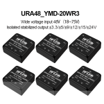
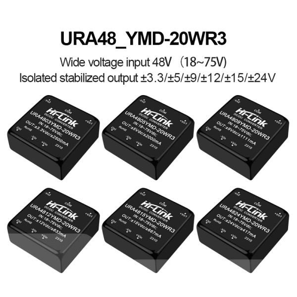
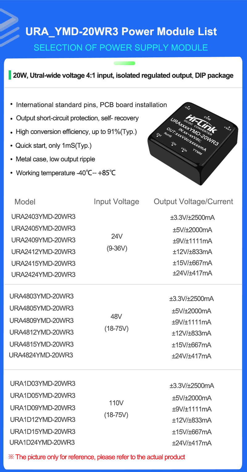
1. Ultra wide range input (4:1), output 20W
2. Conversion efficiency 91%(Typ)
3. Isolation voltage: 1500VDC
4. Ultra low standby power consumption: 0.036W (typical)
5. Ultra fast start: 1mS (typical)
6. Operating temperature range :-40°C~+85°C
7. Output protection: short circuit protection, over current protection, over voltage protection
8. Metal case, low output ripple
9. International standard pin, PCB board in-line installation
10. It is sealed with high quality environmental protection waterproof and thermal conductive glue, moisture proof and vibration proof, and meets the requirements of waterproof and dust proof IP65.
11. High reliability, long life design, long continuous working time
Enviroment Condition
| Project name |
Qualification |
Unit |
Notes |
| Working enviroment temperature |
-40—+85 |
℃ |
|
| Storage temperture |
-40—+125 ℃ |
℃ |
|
| Relative humidity |
5—95 |
% |
|
| Heat dissipation mode |
natural cooling |
|
|
| Atmospheric pressure |
80—106 Kpa |
Kpa |
|
| Vibrate |
Vibration coefficient 10~55Hz,10G,30min. along X,Y,Z |
|
Meet the requirements of secondary road transportation |
Input Characteristics
| Item |
Working conditions |
Min. |
Typ. |
Max. |
Unit |
|
Input current
(full load/no load)
|
24VDC Input Series |
±5V/±9V |
- |
957/25 |
980/35 |
m'A |
| ±12V |
- |
926/1 |
947/2 |
| ±15V |
- |
926/1 |
937/2 |
| ±24V |
- |
916/1 |
937/2 |
| 48VDC Input Series |
±5V/±9V |
- |
484/1 |
496/1.5 |
| ±12V |
- |
458/1 |
469/1.5 |
| ±15V |
- |
458/1 |
469/1.5 |
| ±24V |
- |
458/2 |
469/1.5 |
| Reflection ripple current |
|
-- |
|
40 |
-- |
m'A |
|
Impulse voltage
(lsec.max)
|
24VDC Input Series |
|
-0.7 |
-- |
50 |
VDC
|
| 48VDC Input Series |
|
-0.7 |
-- |
100 |
| Start Voltage |
24VDC Input Series |
|
- |
- |
9 |
| 48VDC Input Series |
|
- |
- |
18 |
|
Input undervoltage protection
|
24VDC Input Series |
|
5.5 |
6.5 |
- |
| 48VDC Input Series |
|
12 |
15.5 |
- |
| Input filter type |
|
PI type |
| Hot plugged |
|
Non-support
|
Output Characteristics
| Project name |
Working and testing condition |
+Vo1 |
-Vo2 |
| |
|
Min. |
Typ. |
Max. |
Min. |
Typ. |
Max. |
| Output load |
load percentage |
0% |
- |
100% |
0% |
- |
100% |
|
Output voltage accuracy
|
|
- |
±1.0% |
±2.0% |
- |
±2.0% |
±3.0% |
|
Linear adjustment rate
|
input voltage range |
- |
±0.2%
|
±0.5% |
- |
±1.5% |
±2% |
|
Load adjustment rate
|
20%-100% rated load, balanced load |
- |
±0.5% |
±1.0% |
- |
±4.0% |
±5.0% |
| Ripple & Noise |
Pure resistive load,20MHz broadband, peak to peak, 5%-100% load |
- |
50mVp-p |
80mVp-p |
- |
50mVp-p |
80mVp-p |
| Start time delay |
|
- |
1ms |
- |
- |
1ms |
- |
| Input vlotage adjustment |
input voltage range |
- |
- |
±10% |
- |
no adjustment |
- |
| Dynamic response step deviation |
25% nominal load step
|
- |
±3.0% |
±5.0% |
- |
±3.0% |
±5.0% |
|
Dynamic response recovery time
|
- |
300μs |
500μs |
- |
300μs |
500μs |
| Output overvoltage protection |
full voltage input range |
110%Vo |
- |
160%Vo |
|
|
|
| Output overcurrent protection |
full voltage input range |
110%lo |
150%lo |
200%lo |
|
|
|
| Output short circuit protection |
full voltage input range |
|
|
sustainable, self-recovery |
|
|
|
| |
|
|
|
|
|
|
|
Note:
(1) For product model with output voltage ±5VDC or ±9VDC , the maximum output voltage accuracy is ±5% under 0% - 5% load condition
(2) When tested according to the 0%-00% load working condition, the load adjustment rate is ±5%
(3) 0%-5% load ripple & noise less than or equal to 5% Vo. Ripple and noise test method, Twisted pair test method, can add capacitive load at the output to reduce light load ripple
Typical Application Circuits


EMC parameter recommendation
| Component No. |
Function |
Recommended value |
| Fuse |
Protest the circuit from damage when the module is abnormal |
Access the corresponding fuse accrding to customer needs |
| MOV/Varistor |
Protest the circuit from damage when the module is abnormal |
14D560K |
| LDM1/Common mode inductance |
EMI Filtering |
Inductance: 10mH |
| CO,C1 Ceramic capacitors |
Filter capacitor |
1uF/50V |
| E1,E2 Electrolytic capacitor |
Filter capacitor |
100uF/50V |
| LDM2/Differential mode inductance |
EMI filtering |
4.7-68uH |
| CY1/Y2 Capacitance |
|
1nF/250vAC |
Notes:
* Fuses and varistors are basic parts of protection circuits (required).
* If the certification is required, the safety capacitor and common mode inductance cannot be omitted.
Output filtering

For usual requirements of ripple and noise, the peripheral recommendation is only C2;
For strict requirements of ripple and noise, the above circuit is recommended. Notes:
(1) C2, C3 use high frequency low resistance electrolytic capacitor, and the total capacity can not exceed the maximum capacitive load indicated in the manual, otherwise the module will not start normally. (2) When the capacitive load is used, the minimum load of 3% must be guaranteed, otherwise the module output will be abnormal.
| Component No. |
Function |
Recommended value |
| LDM3/Common mode inductance |
Adjust the output ripple voltage |
Inductance: 0.47-4.7uH according to the debugging result |
| LDM4/Common mode inductance |
Adjust the output ripple voltage |
Inductance: 0.47-4.7uH according to the debugging result |
| C2,C3 Electrolytic capacitor |
Ripple voltage filtering |
68-220uF/50V |
| C4 Ceramic capacitors |
Ripple voltage filtering |
1uF/50V |
Dimension and Weight

| 1 |
2 |
3 |
4 |
5 |
6 |
| VIN- |
VIN+ |
VO+ |
TRIM |
GND |
CTRL |
| Input negative |
Input positive |
Output positive |
Voltage regulator |
Output negative |
Remote end |