Download files:
https://d.hlktech.net/Mobile/Download
Product Feature
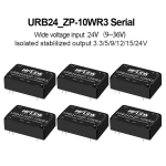
1. Wide input voltage range 4:1, isolated regulated output 10W
2. Isolation voltage 1500VDC
3. Transfer efficiency up to 91%
4. Quick Start:1mS(Typ)
5. Operating temperature range :-40°C~+85°C
6. Small SIP package, metal case, low output ripple
7. International standard pin,direct installation of PCB board
8. Input undervoltage protection, output short circuit, overcurrent, overvoltage protection
General Features
| Project |
Operating conditions |
Min. |
Typ. |
Max. |
Unit |
| Insulation voltage |
Input-output, test time is 1 minute, leakage current is less than 1mA |
1500 |
-- |
-- |
VDC |
|
Insulation resistance
|
Input-output,insulation voltage : 500VDC |
1000 |
-- |
-- |
MΩ |
| Isolation Capacitor |
Input-output,100KHz/0.1V |
-- |
1000 |
-- |
pF |
| Operating temperature |
Reference temperature derating curve |
-40 |
-- |
+85 |
℃ |
| Storage temperature |
|
-40 |
-- |
+125 |
| Maximum temperature of the shell during operation |
|
-- |
-- |
+100 |
| Storage humidity |
No condensation |
5 |
-- |
95 |
%RH |
| Pin soldering temperature |
The solder joint is 1.5mm away from the shell, 10 seconds |
-- |
-- |
+300 |
℃ |
| Switching frequency |
PWM mode |
-- |
250 |
-- |
KHz |
| Viberation |
|
10-55Hz,10G,30Min.alongX,YandZ |
| Shell material |
|
Aluminum shell |
| Minimum time between failures |
MIL-HDBK-217F@25℃ |
-- |
2X10⁵ |
-- |
Hrs |
Input Characteristics
| Item |
Working conditions |
|
Min. |
Typ. |
Max. |
Unit |
| Input current (full load/ no load) |
24VDC Input Series |
3.3V |
- |
402/1 |
413/2 |
mA |
| others |
- |
490/1 |
502/2 |
| 48VDC Input Series |
3.3V |
- |
201/0.5 |
207/1 |
others
|
- |
245/0.5 |
251/1 |
| 110VDC Input Series |
3.3V |
- |
87/0.3 |
90/0.5 |
others
|
- |
100/0.3 |
109/0.5 |
| Reflected ripple |
24VDC nominal input series, nominal input voltage |
-- |
40 |
-- |
|
| 48VDC Input Series |
-- |
30 |
-- |
| 110VDC Input Series |
-- |
20 |
-- |
| Impulse voltage (Isec.max) |
24VDC Input Series |
-0.7 |
-- |
50 |
VDC |
| 48VDC Input Series |
-0.7 |
-- |
100 |
| 110VDC Input Series |
-0.7 |
-- |
200 |
| Starting voltage |
24VDC nominal input series, nominal input voltage |
- |
- |
9 |
| 48VDC nominal input series, nominal input voltage |
- |
- |
18 |
| 110VDC nominal input series, nominal input voltage |
- |
- |
40 |
| Input undervoltage protection |
24VDC nominal input series, nominal input voltage |
5.5 |
6.5 |
- |
| 48VDC nominal input series, nominal input voltage |
12 |
15.5 |
- |
| 110VDC nominal input series, nominal input voltage |
32 |
36 |
- |
| Startup time |
Nominal input voltage and constant resistance load |
|
- |
1 |
- |
mS |
| Input filter type |
|
|
PI type |
| Hot plugged |
|
|
Non-support
|
| Remote control terminal(Ctrl)* |
Module turned on |
|
Ctrl floating or connected to TTL high level (3.5-12VDC) |
| |
Module turned off |
|
Ctrl is connected to GND or low level (0-1.2VDC) |
| |
Input current at shutdown |
|
- |
0 |
1 |
mA |
| Note: *Ctrl control pin voltage is relative to input pin GND |
Output Characteristics
| Project name |
Working and testing condition |
+V01 |
-V02 |
| Min. |
Typ. |
Max. |
Min. |
Typ. |
Max. |
| Output load |
load percentage |
0% |
- |
100% |
0% |
- |
100% |
| Output Voltage Accuracy |
|
- |
±1.0% |
±2.0% |
- |
±2.0% |
±3.0% |
| Linear adjustment rate |
input voltage range |
- |
±0.2% |
±0.5% |
- |
±1.5% |
±2.0% |
| Load adjustment rate |
20%~100% rate
load, balanced
|
-- |
±0.5%
|
±1.0% |
- |
±4.0% |
±5.0% |
| Ripple & Noise |
Pure resistive load, 20HMz bandwidth, peak-to-peak |
-- |
50mVp-p |
80mVp-p |
- |
50mVp-p |
80mVp-p |
| Startup delay time |
|
|
- |
1ms |
- |
- |
1ms |
- |
| Output voltage regulation |
Input voltage range |
- |
No adjustment end |
- |
- |
No adjustment endNo adjustment end |
- |
| Dynamic response step deviation |
25% nominal load step |
- |
±3.0% |
±5.0% |
- |
±3.0% |
±5.0% |
| Dynamic response recovery time |
- |
300μs |
500μs |
- |
300μs |
500μs |
| Output overvoltage protection |
Full voltage range input |
110%Vo |
- |
160%Vo |
|
|
|
| Output overcurrent protection |
Full voltage range input |
110%Io |
150%Io |
200%Io |
|
|
|
| Output short circuit protection |
Full voltage range input |
Sustainable, self-healing |
| Note: ① For product models with output voltages of ±5VDC and ±9VDC, under 0%-5% load conditions, the maximum output voltage accuracy is ±5%; ②When tested under the working conditions of 0%-5% load, the index of the load adjustment rate is ±5%; ③0%-5% load ripple & noise less than or equal to 5% Vo. Ripple and noise test method Twisted pair test method, you can add capacitive load at the output to reduce light load ripple. |
Note:
1、The above is only a list of typical products. If you need products beyond the list, please contact our sales. 2、The maximum capacitive load indicates the maximum capacitive load that + VO or - vo can be connected to,If the value is exceeded, the product will not start normally..

Typical Application Circuits

Notes:More details please feel free to contact hi-link team.

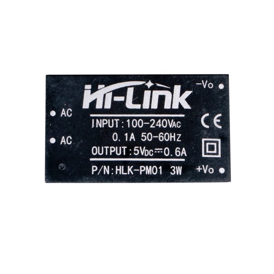
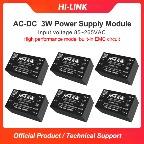
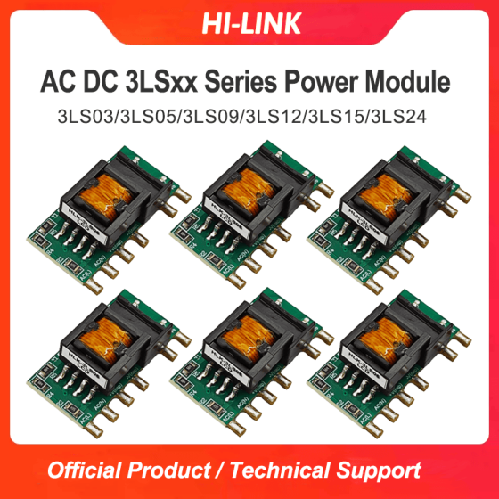
 DC To DC Module
 Radar Sensor Module
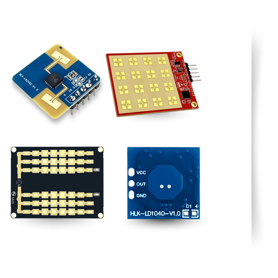 Wireless WIFI Module
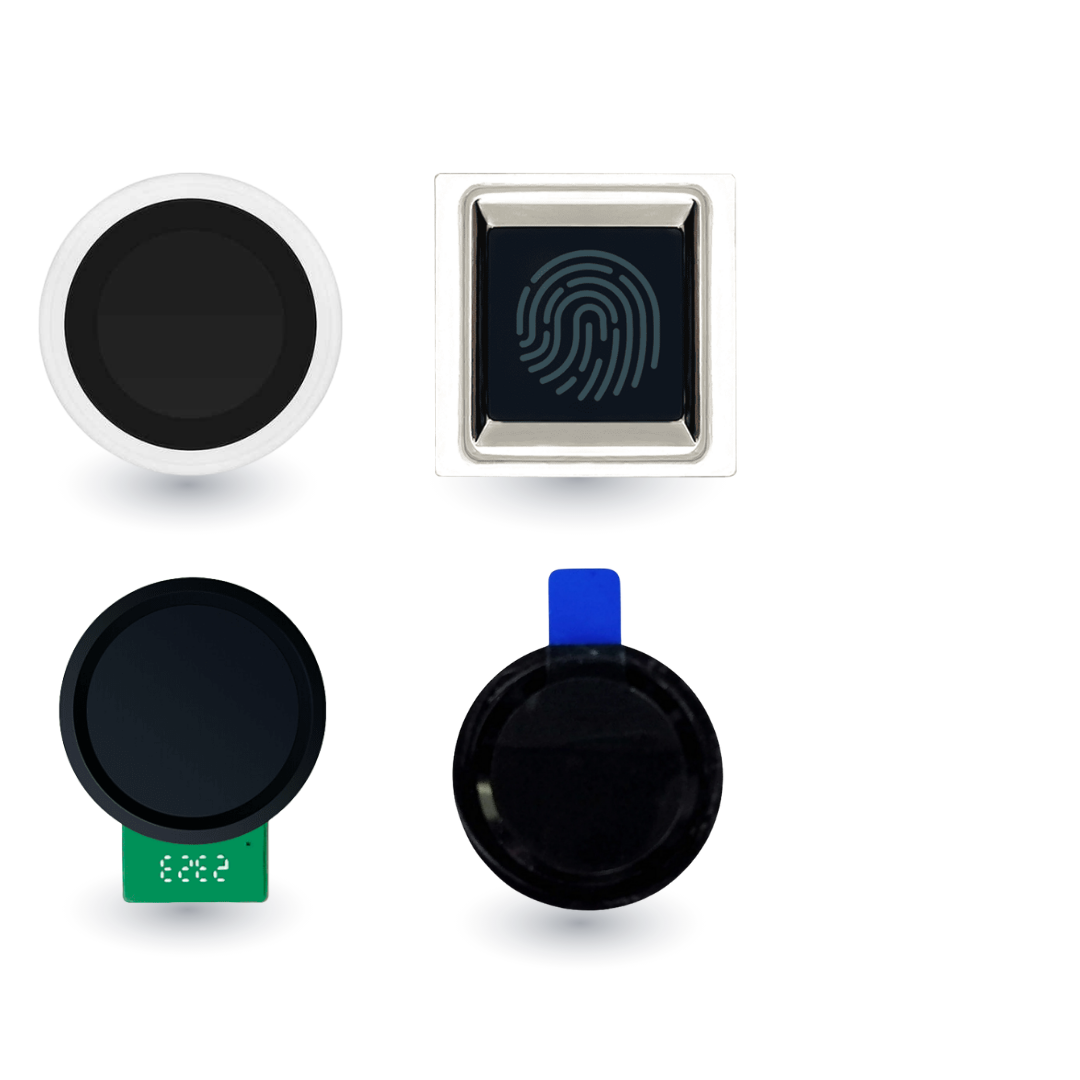
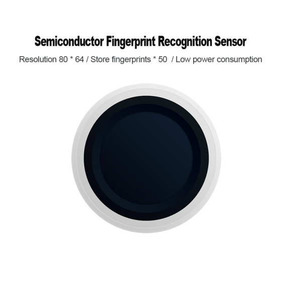
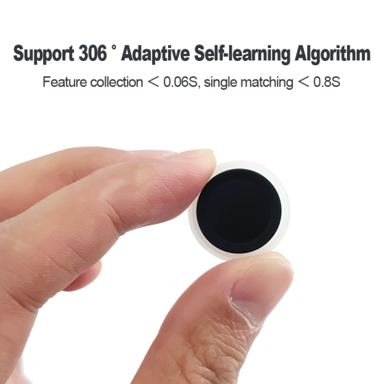
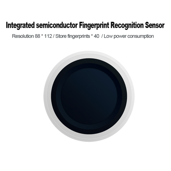
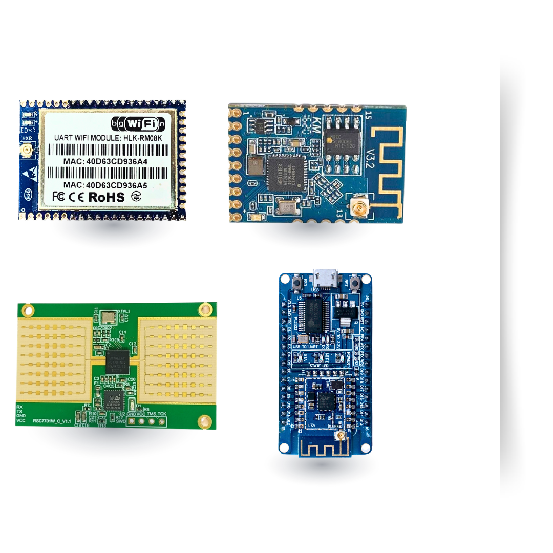 Finger Print Module